Friday, October 27, 2006

Laser Welding

Background

When the laser’s concentrated energy is used for welding it gives many advantages over conventional resistance methods. The technology is already spreading through the automotive industries of America and Europe.

The Process

The process is a non-contact one that directs laser outputs of 2-10 kW into a very small area. This means that power levels in excess of 103-105Wmm-2 are produced on the surface of the parts to be welded. The laser beam makes a ‘keyhole’ and the liquid steel solidifies behind the traversing beam, leaving a very narrow weld and heat affected zone (HAZ). The weld is approximately 1 mm wide and the surrounding material is not distorted. Because the weld bead is small, there is usually no need for finishing or re-working and this reduces costs. In the case of zinc-coated steels, the narrow weld also means that it is protected by the sacrificial galvanic corrosion in the adjacent zinc layers. As access for welding is required from one side only, many different joint configurations are possible that were previously unavailable. And so laser welding opens doors to innovative joint designs.

Capacity and Flexibility

One company that uses laser welding is British Steel (UK). A 5 kW carbon dioxide laser and beam manipulation system has been installed at the Welsh Laboratories’ Customer Technical Centre. This system works on the ‘flying optics’ principle where the workpiece remains fixed and the beam is manipulated into the desired position by a series of moving mirrors. Cutting can be done over an area 6.25m2, and welding along a securely clamped length of 2.25 m enables long seam welds to be produced.

Custom Formulations

One application which lends itself readily to laser welding is the manufacture of tailored blanks. Laser welding allows manufacturers to provide the material properties in the areas where they will be used to their best effect, where material utilisation is maximised, where the total number of build operations are minimised, whichever they choose.

Door Panels

Because of the high formability levels of laser welds, the desired combinations of steel strength, thickness and/or coating type can be laser welded together as flat sheets and then pressed into the required panel shape. The rear inner door panel shown (figure 1) contains three different steels. The lower part of the door con­tains an area of hot-dip galvanised steel, which protects against corrosion in the most vulnerable spot. The right hand side contains an area of high strength, uncoated steel that replaces many of the reinforcement parts, which are currently welded on after pressing. This steel also provides the necessary strength for door hinges and door mirrors. The rest of the door is made of iron-zinc coated steel.

Figure 1. Inner door panel made up from 3 different steels that have been laser welded together.

Chassis Members

Another interesting application is using composite blanks for chassis members, for example the structural areas within the bodyshell that are conventionally made from single thickness steel and strengthened in critical areas by welding on stiffening assemblies, after the forming operations. By laser welding together areas of thicker or higher strength steels with thinner gauge steels, a lighter structure (with higher strength areas only where required) can be produced in a single pressing operation. This negates additional stamping and forming to make the reinforcement parts and the resistance welding together of the various parts.

Researchers at Welsh Laboratories are studying the impact and torsion characteristics of box-hat structures, which are designed to simulate these structural members. Experiments have shown that by laser welding together different thickness steels that are formed into the box-hat structure and then subjected to a simulated 30 mph collision, it is possible to control the areas within the structure that collapse and those that remain intact, thereby providing effective crash management of the vehicle.

Conclusions

The formability of laser welds is the key to the success or failure of a part. Because of the small HAZ, the welds are extremely formable, as long as joint quality is good, and in cupping tests generally give between 80 and 100% of the fracture height of the base material.

Leaf Springs, Better by Design

In addition to new lightweight vehicle bodies, a new weight saving design is available for commercial vehicles. This time it is the turn of the suspension unit, the weight of which is reduced through a spring design that optimises the use of the properties of the steel from which it is made.

Parabolic tapered leaf springs are designed to offer a significant and cost effective weight reduction in previously very high weight components (figure 1). They provide an alternative to traditional laminated leaf springs, offering:

· Approximately 40% weight reduction

· Optimised use of material properties

· Minimum inter-leaf friction and contact, and so the ability to use more durable corrosion protection and improved ride characteristics.

Other benefits include improved fuel economy or load carrying capacity, and reduced road damage for an equivalent axle weight.

In conventional uniform thickness leaf springs, the mid length is the highest stressed region and the thickness of the leaves is designed to accommodate this maximum stress. However, to either side the stress decreases with distance from the centre and the strength of the steel is progressively under used.

Parabolic tapered leaf springs, on the other hand, are designed with a reducing thickness from the centre outwards. The regions to either side operate at a uniform stress level, similar to that at the centre. This allows for maximum use of the material properties, and reducing the section thickness minimises the weight of the spring.

Parabolic tapered leaf springs can be fitted in place of standard laminated leaf springs with very little change to the design of vehicle attachment fixtures. They are produced using conventional metallurgical techniques and spring steels, including 0.6%C-Cr (SAE 5160, BS970:525A58) for thinner sections and 0.6%C-CrMo (SAE 4161, BS970:705A60) for thicker sections. The leaves are produced by hot rolling the tapered section, and then after roll forming they are hardened and tempered to a hardness of approximately 450HB.

For maximum fatigue resistance the leaves are stress peened to develop a high level of beneficial compressive residual stress in the surface. This involves deflecting individual leaves and shot peening while they are in the strained condition. Then they are assembled into the final component, which may comprise a number of parabolic leaves, figure 1. Typical weight savings per spring are shown in table 1.

Table 1. Typical weight savings using parabolic tapered leaf springs.

Application

Weight (kg)

Parallel multi leaf

Weight (kg)

Parabolic

Weight

Saving (%)

Van

7.8

4.4

44

Articulated Vehicle -

Front Axle

103

71

38

Rear Axle

162

90

44

A further development, currently under evaluation to introduce additional weight saving, involves the use of a lower carbon steel that is hardened and tempered to a higher strength level. This lower carbon steel offers a higher heat treated strength combined with the retention of good ductility and toughness. The objective is to use these features to provide improved fatigue resistance and a possible additional 15% weight saving. Increased fatigue resistance is obtained from a combination of higher strength and an improved sub surface compressive stress profile following shot peening.

The hardenability of the new steel is adjusted to ensure a fully martensitic microstructure on hardening, thus producing a ductility level at least equal to that of a traditional spring steel, despite the higher heat treated strength. The spring can be produced with a similar form to that of a standard parabolic tapered leaf spring. Typical heat treated properties, compared with those of a conventional spring, are shown in table 2. In addition, a Weibull analysis of laboratory results shows an improvement it bending fatigue properties obtained from the development grade, compared with a 0.6%C-Cr steel (SAE 5160).

Table 2. Mechanical properties of steel for reduced weight springs.

Steel

0.2% P.S.

(N mm-2)

Tensile Str

(N mm-2)

Elong

(%)

R of A

(%)

Charpy Impact

2mm V

SAE 5150

1290

1430

11

37

10

New Grade

1530

1750

11

41

10

Parabolic tapered leaf springs are produced by Tinsley Bridge of Sheffield (UK), under the name of Taperlite. The latest development described above has the code name Extralite. Both types of spring highlight the potential for component improvement when the use of steel is optimised for a particular application.

Thursday, October 26, 2006

Lacquer and Paint Coatings Analysed by Secondary Ion Mass Spectrometry ( SIMS ) and X-Ray Photoelectron Spectroscopy ( XPS ) – Supplier Data by CSMA L

Background

Many of today’s lacquer and paint coatings are complex multi-component formulations, designed for decorative and/or protective and/or functional applications. Surface analysis methods are important for the study of such coatings e.g.

· Investigation of lacquer and paint delamination (adhesive and cohesive failures).

· Analysis of other coating defects e.g. craters, particulates, changes in cosmetic appearance (e.g. bloom, loss of gloss).

· Evaluation of coating integrity e.g. uniformity and distribution, thickness, homogeneity (phase separation, additive segregation).

Benefits to Customer

· Cost effective - one day of analysis can often identify the coating problem

· Rapid information - clear decisions can be made to take remedial action to improve processes

· Validation of new processes by comparison to predicted models

· Assessment of competitors’ products - reverse engineering

Case Study One: Crater Defects in Lacquer and Paint Coatings

Craters were visible in a melamine-based lacquer coating on a metallised foil. ToF-SIMS was used to analyse a crater with reference to non-cratered lacquer material. The results revealed high levels of caprylate and caprate-based esters of glycerol within the crater. Diagnostic signals for this material include m/z 127+/155+ (CnH2n+1CO+) and m/z 327+/355+/383+ (CnH2n+1C(=O)O-CH2-CH[O(O=C)CnH2n+1]-CH2+) (where n is a mixture of 7 and 9), readily identifiable using the molecular specificity of ToF-SIMS. Glyceride esters can be used in lubricant formulations and the source of this contamination was the coating equipment.

Craters and other defects have also been observed in automotive coatings, illustrating the necessity for stringent cleanliness specifications during the painting process. ToF-SIMS is used routinely to investigate these (see figure 1).

AZoM - Metals, Ceramics, Polymer and Composite : Paint Coatings Analysed by Secondary Ion Mass Spectrometry ( SIMS ) – Supplier Data by CSMA Ltd

Figure 1. ToF SIMS analysis of a crater defect.

AZoM - Metals, Ceramics, Polymer and Composite : Time of Flight Secondary Ion Mass Spectrometry ( SIMS ) data acquired from within a crater in the paint coating – Supplier Data by CSMA Ltd

Figure 2. ToF-SIMS data acquired from within a crater in an automotive coating, showed that a fluorocarbon contaminant had caused localised de-wetting of the surface during paint application, resulting in crater formation.

AZoM - Metals, Ceramics, Polymer and Composite : Time of Flight Secondary Ion Mass Spectrometry ( SIMS ) analysis showing contamination in the paint coating – Supplier Data by CSMA Ltd

Figure 3. The two-colour overlay ToF-SIMS image shows an intense fluorine signal in the de-wetted area (cyan), associated with the fluorocarbon contaminant. Organic species from the paint layer are shown in red.

Case Study Two: Failure of Beverage Can Coatings

SIMS depth profiling was used to study the failure of beverage can coatings on long term shelf storage. The locus of failure was believed to have occurred at the lacquer coating / can wall interface with a suspected corrosion mechanism involved.

SIMS profiles through the lacquer coating and into the steel can substrate revealed the presence of high levels of chlorine at the lacquer/steel interface on cans with poor long-term performance (see below). In contrast, good cans had relatively low levels of chlorine present. In combination with other analyses, the results revealed a corrosion mechanism involving transport of chlorine to potential corrosion sites during storage.

AZoM - Metals, Ceramics, Polymer and Composite : Secondary Ion Mass Spectrometry ( SIMS ) profile through a lacquer coating into steel substrate – Supplier Data by CSMA Ltd

Figure 4. SIMS profile through a the lacquer coating and into the steel substrate.

Case Study Three: Evaluation of Coating Integrity

As a quantitative method, XPS is a valuable tool for the determination of coating uniformity and thickness. This is demonstrated for a functional siloxane coating on a polymer substrate where multi-area XPS analysis (supported by SIMS imaging) showed a reasonably homogeneous siloxane distribution over the polymer surface.

Table 1. XPS analysis of a siloxane coating on a polymer substrate.

Element

Area 1

Area 2

Area 3

Carbon

65.9 + 0.3

66.1 + 0.3

65.0 + 0.4

Oxygen

26.0 + 0.2

25.9 + 0.2

26.2 + 0.2

Silicon

2.5 + 0.1

2.7 + 0.1

2.8 + 0.2

Sulfur

1.4 + 0.1

1.1 + 0.1

1.2 + 0.1

Sodium

2.1 + 0.2

1.8 + 0.2

2.3 + 0.3

Potassium

1.3 + 0.2

0.9 + 0.2

1.3 + 0.3

Calcium

0.1 + 0.1

0.4 + 0.1

0.3 + 0.1

Chlorine

0.07 + 0.02

0.13 + 0.04

0.19 + 0.04

Boron

0.7 + 0.2

1.0 + 0.2

0.7 + 0.3

Nitrogen

Not detected

Not detected

Not detected

Case Study Four: Lacquer/Varnish Coatings on Wood

Depth profiling SIMS and/or SIMS imaging can give an assessment of the effectiveness of different lacquer formulations for varnishing different woods. This is illustrated by a two-colour overlay SIMS image of a varnished wood cross-section which shows the surface film structure and penetration of a UV-lacquer (blue; using a lacquer-specific signal in the SIMS mass spectrum) into a wood (brown; using a wood-specific signal in the SIMS mass spectrum).

AZoM - Metals, Ceramics, Polymer and Composite : Secondary Ion Mass Spectrometry ( SIMS ) analysis showing lacquer coating penetrating into a wood substrate – Supplier Data by CSMA Ltd

Figure 5. Two colour SIMS overlay of a lacquer coating over wood, lacquer shown in blue and wood in brown.

Kyocera Expands MEC Tool Series Range of Cutting Tools

Kyocera Corporation is pleased to announce a new development in the field of cutting tools. Inserts made from new materials, newly designed cutters and a range of other new items will be offered beginning November 22, 2004 as part of Kyocera’s popular “MEC Tool Series” that was introduced in September 2003. These new additions will dramatically expand the repertory of products Kyocera offers. There will now be 34 items in two material types available in the insert range, where previously there were three items of a single material type, as well as 31 end mill items and six cutter items.

Background

Production and manufacturing plants are constantly being asked to produce smaller and more complicated designs for machine parts. To produce these parts, they need tools that offer even higher levels of precision and efficiency. In September 2003, Kyocera introduced its “MEC Tool Series,” a series of metal cutting tools that feature a newly designed holder called the “Ultra Hurricane End Mill,” which realizes the strong rigidity and durability essential for stable work in steel and stainless steel cutting processes, and the “PR830” insert that has a PVD coating and offers exceptional wear-resistance. These tools have served to dramatically enhance working efficiency by eliminating the need for the separate finishing work previously required, and thus have been extremely well received by many factories involved in metal cutting.

Now, Kyocera has dramatically expanded and enhanced the MEC Tool Series repertory with the addition of inserts made from new materials suitable for cast iron cutting work, the addition of newly designed cutters that enable the smooth working of flat surfaces on large-scale work materials, the expansion of the “Corner R” line-up of inserts and the introduction of newly designed chipbreakers that realize even lower cutting resistance. With this expanded line, Kyocera aims to provide its customers with the wide variety of cutting processes they demand, while also shortening work time and reducing overall costs.

Features of new additions to the “MEC Tool Series”

1. “PR905” with PVD Coating for cast iron

Kyocera’s proprietary developed FS coated (TiAlN) film makes for a smoother insert, as well as improved wear-resistance and stability at high temperatures. This also expands the service life of inserts. Moreover, the use of a high-strength carbide substrate that exhibits outstanding strength and plastic deformation resistance works to curb the progression of wear caused by chipping, and realizes high efficiency and stability in milling (circular cutting) operations on gray cast iron and nodular cast iron.

2. Newly designed “Ultra Hurricane Face Mill” cutter

A new type of face mill has been added to the end mill series line-up that is capable of working with large diameters from φ40mm-φ100mm. Previous end mills were only capable of working with diameters up to 40mm. This will facilitate highly efficient cutting processes for those large surface areas that cannot be worked using end mill cutting processes.

3. Expanded line-up of “Corner R” inserts

The line-up of Corner R inserts (with rounded angles) now includes a total of six items: the previous R0.8 insert with 0.8 mm radius, and the new R0.4, R1.2, R1.6, R2.0, and R3.1. This new line-up of designs caters to users’ various cutting needs. The small-diameter Corner R inserts that produce a sharp edge are good for finishing work, while the larger-diameter Corner R inserts have a long service life and offer stable cutting.

4. Introduction of low-resistance “JS” chipbreaker

The new “JS” chipbreaker has been added to the chipbreaker design line-up. It reduces the cutting resistance of inserts during cutting by around 20% compared with previous chipbreakers, and realizes smooth cutting of sharp edges on low-carbon steel and stainless steel materials. Along with providing stable operation like its predecessor “JT” chipbreakers, this low-resistance “JS” chipbreaker can cater to a wide variety of cutting applications.

Wednesday, October 25, 2006

Kobe Steel’s Aluminium Side Impact Door Beams Finding Increasing Applications

Kobe Steel, Ltd.'s aluminium side-impact door beam is being used in Mitsubishi Motor Corporation's Lancer Evolution VIII MR, a four-door sports sedan that went on sale earlier this year in Japan. This is the first time the aluminium extrusion has been adopted by Mitsubishi. In comparison to door beams made of high strength steel sheet rolled into the form of a pipe, aluminium side-impact beams reduce the weight of a four-door car by roughly 3.5 kg.

Owing to growing demand, production of 100 metric tons a month is expected to rise to 150 metric tons a month in the second half of fiscal 2004. Aluminium side-impact beams have been used in Japanese cars for over 10 years in 10 models amounting to 1.7 million automobiles.

Door beams protect passengers by absorbing the energy in side collisions. While side collisions in traffic accidents occur relatively less frequently, side collisions of passenger cars by SUVs, which are growing in popularity, can result in serious accidents, heightening the necessity for side-impact beams. Aluminium is drawing greater attention as automakers seek to make lighter cars to improve mileage and reduce emissions while maintaining safety.

Kobe Steel is Japan's only manufacturer of the aluminium beams. It holds 15 patents in Japan, five in North America, and five in Europe. In addition to domestic carmakers, Kobe Steel supplies a number of Japanese automotive transplants.

The first applications of the aluminium beams were in Honda Motor Co., Ltd.'s all-aluminium NSX and Nissan Motor Co., Ltd.'s Rasheen, an SUV. As Japan's top manufacturer of aluminium for cars, Kobe Steel aims to further expand applications of aluminium side-impact beams. Other automotive aluminium products that Kobe Steel makes are sheet for body panels and forgings for suspension systems.

Tuesday, October 24, 2006

Kinetic Metalization – A Technology for Low Temperature Spraying of Metal Coatings

Background

Inovati, a Santa Barbara-based company, has successfully developed a low-pressure metal deposition technique that has won it an R&D 100 Award for 2002. Known as Kinetic Metalization, it is capable of depositing a variety of metals as dense coatings onto metal surfaces, without needing prior surface preparation. Copper, stainless steel, nickel, chromium, aluminium, cobalt, titanium, niobium and other metals can all be deposited, as well as alloys based on these metals and braze powders. These coatings can also be sprayed on to ceramic substrates.
Origins of the Technology

The original concept was first introduced by Samuel Thurston in 1902 and was rediscovered by Russian researchers in the 1980s. The process was then developed throughout the 1990s by Inovati, principally by Dr Ralph Tapphorn and Howard Gabel. They perfected and patented the process, developing special apparatus that uses an inert gas to spray metallic powders on to substrates, so eliminating deposition-induced oxide formation.
Equipment Required for Depositing Coating by Kinetic Metalization

Kinetic Metalization is performed with a two-phase, converging-diverging deposition nozzle that accelerates and triboelectrically charges metal particles contained in an inert carrier gas, usually, helium, and a dynamically-coupled debris recovery nozzle that captures surface contaminants and accelerant gas for recycling and reuse.
How the Coating Process Works

Once accelerated to high speed and electrically charged, the particles are directed to a substrate, a mandrel, or into a mould. Subsequent high-speed collision of the metal particles causes very large strain (approximately 80% in the direction normal to impact) in the particles. This deformation results in a huge increase in particle surface area (approximately 4000, producing a new surface that is oxide-free. When these active surfaces come into contact, pure metallurgical bonds are formed.
Using the Process to Abrade and Produce Free Standing Shapes

However, the process is not limited to depositing surface coatings – Kinetic Metalization can be used to produce freestanding shapes. This is achieved via the same process, but the thin coating is allowed to build up through repeated passes of the application gun. The shapes are generated by manipulating the passes of the application gun with a computer-controlled positioning system. First, a description of the part is produced as a CAD file and then the file converted into a stereolithographic file (G Code). This is then used to control the positioning system. The same methodology can also turn the process into a subtractive tool - by spraying a purely abrasive powder, such as SiC, it will act as an efficient abrasive/subtractive spray method.
Advantages of Low Processing Temperatures

According to James Intrater, Principal Engineer at Inovati, the feedstock material for Kinetic Metalization is powdered metal, and since it is deposited at well below its melting point, the coatings exhibit very fine grain size and additionally avoid heat distortion of the item being coated. This is particularly critical in spraying nano-powders and amorphous metals, where in the former the heat will instigate grain growth, and in the latter will cause crystallisation.
Advantages of the Kinetic Metalization Process

Kinetic Metalization has been used to spray very fine grain size powders and amorphous aluminium. It has also sprayed nickel, chromium, niobium and copper alloys while preserving a very fine microstructure, something that thermal spraying, such as HVOF, does not allow. Furthermore, compared to other deposition methods such as electroplating, because Kinetic Metalization is a direct spray jet, masking of the workpiece is not required.
Carrier Gases

With regards to the type of gas used as a carrier, helium is used as it is inert and can transport the powder at very high speed. Other gases can be mixed with helium to enhance deposition.
Spray Nozzles

The standoff distance from the nozzle to the substrate is typically 1.25cm and the spray nozzles must be made of an abrasion resistant material (e.g. ceramic) and be specifically internally configured to produce the optimum set of spray dynamics. Multiple nozzles can be used in groups or a single nozzle can have a very large diameter, should one wish to coat particularly large areas or numbers of parts.
Kinetic Metalization versus Cold Spraying

Compared to the Cold Spray process developed by Sandia National Laboratories, Inovati has worked out a host of deposition instrumentation and deposition parameters so as to be the first low-temperature spray technology that is fully geared toward production spraying, and capable of very high reliability deposits.

Furthermore, the Sandia National Laboratories patented process is limited to spraying powders below their thermal softening point and requires that all powders be sprayed through a supersonic nozzle. As such, cold spray will exhibit comparatively low deposition efficiencies and inhibits the ability to tailor the properties of coatings and spray-formed objects.

Iron Ore Trends for 2002

China’s thriving steel industry looks set to import more iron ore than ever before, according to a new report from AME Mineral Economics. The report goes on to say that China’s iron ore imports in 2002 beat the previous record by around 20 million tonnes and, despite a flagging economy, Japan also increased its imports by almost three million tonnes, posting the second highest level in well over a decade at 120 million tonnes.

The report also shows how the iron ore industry has responded to the rapidly evolving market - and to the long term pressures on prices - by reducing costs and increasing output. Cost reduction forces gained momentum as early as 2000 as the industry’s giants embarked on a major consolidation drive. By 2002 CVRD, Rio Tinto and BHP Billiton had captured more than 70% of seaborne trade, compared with 50% in 1999. This consolidation had a marked effect - during the past two years the big three have reduced costs by 13%, while the other top ten producers shaved an average 8% from their cash production costs.

AME’s analysis indicates that ore transport and port costs continue to be big cost factors for the iron ore industry, In 2002 transport and port costs constituted 52% of the total costs, while the actual mining activities made up only 21%, ore processing 17% and royalties 10%.

Monday, October 23, 2006

Investment Casting – History, Materials and The Future

Background

Investment casting is a versatile process, used to manufacture parts ranging from turbocharger wheels to golf club heads, from electronic boxes to hip replacement implants. The industry, though heavily dependent on aerospace and defence outlets, has expanded to meet a widening range of applications. Modern investment casting has its roots in the demands of the Second World War, but it was the adoption of jet propulsion for military and then for civilian aircraft that stimulated the transformation of the ancient craft of lost wax casting into one of the foremost techniques of modern industry.

Investment casting expanded greatly worldwide during the 1980s, in particular to meet growing demands for aircraft engine and airframe parts. Today, investment casting is a leading part of the foundry industry, with investment castings now accounting for 15% by value of all cast metal production in the UK.

Modernising of an Ancient Art

Lost wax casting has been used for at least six millennia for sculpture and jewellery. About 100 years ago, dental inlays and, later, surgical implants were made using the technique. World War II and then the introduction of gas turbines for military aircraft propulsion transformed the craft into a modern metal-forming process. Turbine blades and vanes had to withstand higher temperatures as designers increased engine efficiency by raising inlet gas temperatures. Initially, forged alloy steels were used but soon more heat-resistant alloys were needed, leading to the development of special nickel-base and to a lesser extent cobalt-base alloys, which became known as ‘superalloys’. Further alloy developments allowed turbine operation at even higher temperatures and greater efficiencies, but the materials became more refractory and less forgeable by traditional methods although becoming more costly to machine (particularly to the demanding airfoil configurations).

Modern Demands of a Casting Process

Against this background, attention turned to lost wax casting to produce accurately shaped blades. In meeting this challenge, four key problems had to be solved:

· Castings had to be reproducible within close dimensional limits

· Castings had to be produced in high melting point alloys

· There had to be high standards of metallurgical quality

· Costs had to be lower than for alternative techniques.

The Beginnings of Investment Casting

It was the successful solution of these problems that laid the foundation for the modern investment casting industry.

One buoyant niche market relies on special techniques (including hot isostatic pressing after casting) to produce components with fatigue strengths equal to forgings. Castings can now be made for applications with oscillating stress.

What Materials are Used in Investment Casting

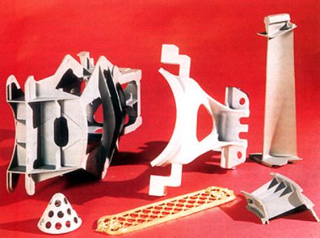
Investment casting is used for a wide range of applications, figure 1. Small parts form the bulk of production, but very large components (with over 1.2m envelope edge and weighing over 250kg) can also be made commercially. Nickel and cobalt-base superalloys account for 50% of total output by value, steels (of all types) account for 35%, aluminium accounts for about 10%, and copper and titanium alloys make up a large part of the remaining 5%.

AZoM - metals, ceramics, polymers and composites : components produced by investment casting.

Figure 1. A range of components produced by investment casting.

Superalloys

Gas turbine engine blades and nozzle guide vanes are exposed to very demanding conditions. Some of the most advanced materials and processes have been developed for such applications, which are now a major outlet for vacuum cast nickel-base superalloys. Complex coring technology to promote internal cooling is used routinely and effectively in blade applications. The metallurgical achievements of the directional solidification and single crystal techniques are used cost effectively in volume production, but most precision-cast airfoil components downstream of the highest temperature/pressure stages are still based on equi-axed castings.

Large, complex thin-walled engine carcass parts such as diffuser housings and combustors are made by investment casting, producing parts up to 1500mm across and 600mm deep. These are replacing sheet metal fabrications, not only because they are more cost effective but because they also provide a high rigidity monolithic component with superior service characteristics. Investment cast integrally-bladed turbine wheels for smaller turbine engines, offering large cost savings over mechanical fabrications, have been widely adopted.

Recently, demand has been growing for investment cast blades and fans to be used in land based turbines for power generation. Components are larger and operate at lower temperatures, but the growing demand parallels that for aero engine parts in the 1980s. This sector of the market has in fact sustained airfoil investment casters over the past few years when aircraft demand dropped.

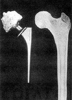
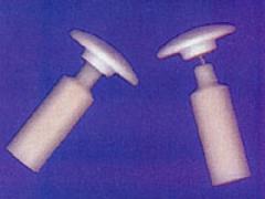
In a different field altogether, there is a long established market for hip replacement prostheses made from cobalt-base superalloys formed by investment casting.

Steels

The variety of steels used and of parts cast has increased dramatically as designers and engineers have realised the potential of investment castings. The aerospace, armament, automotive, food, petrochemical, nuclear, textile, valve and pump, and other general engineering industries all use the technique. From golf club heads to gearbox parts for automotive applications, from bicycle cam forks to various gears and cam components, investment casting with wear resistant steels covers them all.

Aluminium Alloy Castings

Aluminium alloys are the most, widely used nonferrous investment castings, in the fields of electronics, avionics, aerospace, pump and valve applications and military command equipment. Originally light alloy castings were quite small, but much larger sizes - as much as 800-1000mm envelopes - are now regularly cast. Improved shell systems and casting techniques have allowed wall thickness to be progressively reduced in order to minimise weight. Interest in improved strength premium quality aluminium-silicon-magnesium alloy castings means casters can now offer castings for demanding applications, such as airframe components.

Titanium Alloy Castings

Titanium alloy investment castings are produced for static structural applications requiring metallurgical integrity with high fracture toughness, at sizes up to at least 1250mm. In the US, 300-450mm long hollow compressor blades are cast in titanium alloy, and both the US and Japan manufacture titanium golf club heads! These form a substantial part of the titanium investment casting market.

Environmental Issues

There have been numerous developments in the investment casting process recently, but the greatest change has come from the need to meet the environmental standards laid down in the Environment Protection Act. In shelling, the primary coat (which comes in direct contact with incoming molten metal) is a highly refractory material, typically zircon, applied with a silica sol water binder. In the US subsequent coats generally also have water-based binders but most UK and continental European foundries traditionally use alcohol-based (ethyl silicate) binders, generally with molochite-type stuccos (plasters). VOC emissions from these binders may exceed permitted limits, and many UK foundries are now changing to water binder systems. Rapid drying water binders are being introduced to prevent any slowing of production.

Expanding Markets

Investment casting markets increased steadily over 40 years to the mid 1980s, when demands for new aircraft boosted both the sales of investment castings and industry capacity. The market continued expanding up to 1990, when annual worldwide turnover reached about £3,000 million. Over the next few years, aerospace and defence demands dropped and output decreased, in some countries by as much as 15-20%. Since 1994, however, general commercial demand has picked up and with recent aircraft orders turnover is approaching its previous high.

Based on data published in early 1996, annual world turnover is estimated as £2,800 million. North America (essentially the US) accounts for about half, Western Europe a quarter, and the Pacific Rim countries 20%. Within Western Europe, the UK remains the biggest national producer with output of £300 million, followed by France (£185 million) and Germany (£135 million). Britain is home to about 50 of the 125 or so western European investment casting foundries, employing roughly 5,500 people in an industry which leads the European community.

The Outlook for Investment Casting

Investment casting is recovering lost ground. Commercial business is up, land-based power generation demand is buoyant and the aircraft market is increasingly active. Growth can be expected until the end of the century and beyond if the industry can promote itself well enough.

The Automotive Market

European investment foundries should look to opening up the automotive market to investment castings. Realistic pricing of standard parts, however, can only come with sufficient automation to deal cost effectively with demand. But foundries will only invest in such equipment when orders are secured. Industry competition - particularly price competition - is intense and likely to get tougher. The process serves an international market in which there are growing imports from one region to another.

Threats from Alternative Materials

Other materials and processes (especially other precision casting processes) pose threats. Superalloys have remarkable temperature capabilities through optimisation of composition, advanced processing techniques and complex internal cooling, but further developments are limited by the melting points of nickel and its alloys. To an industry so reliant on cast nickel-base superalloys, aluminide intermetallics, oxide dispersion strengthened materials and engineering ceramics are a serious threat.

The Aluminium Sector

For the expanding aluminium sector of the investment casting market, traditional alloys will remain dominant. Reinforced composites, aluminium-lithium etc. will only find niche applications.

Investment Casting in the UK

Investment casters in the UK produce about 12% of world production, and by value the industry accounts for 13-14% of UK casting output (significantly more than steel castings). These are impressive figures and confirm the growing importance of investment casting.

Iron

Chemical Formula

Fe
Background

Iron has been known since prehistoric times. It makes up 5% of the Earth's crust and is second in abundance to aluminium among the metals and fourth in abundance behind oxygen, silicon, and aluminium among the elements. It is also found in the sun and many types of stars in considerable quantity. Iron is found native only in the form of meteorites known as siderites. Its common ores are magnetic pyrites, magnetite, hematite (Fe2O3) and carbonates or iron.

Iron is obtained from its ores by fusing to drive off the oxygen, sulphur, and impurities. Melting is carried out generally in a blast furnace, directly in contact with the fuel and with the limestone as a flux. These combine with the quartz and clay, forming a slag, which is readily removed. The product is crude pig iron, and further remelting and refining produces commercially pure iron.

Iron metal is greyish in appearance and is very ductile. Small amounts of carbon will significantly alter the properties of iron. Iron containing 0.15% of chemically combined carbon is termed ‘steel’. It is very reactive chemically (it is attacked by most acids), corrodes readily which is accelerated by the presence of moist air or elevated temperatures.

Iron in its pure state is allotropic, existing as a solid in two different crystal forms. These forms and occurrence are outlined below:

· From subzero to 700°C iron has a body centred cubic crystal structure, identified as alpha (a) iron, and is magnetic.

· From 700°C to 928°C iron changes from alpha (a) iron to beta (b) iron, the crystal structure remains unchanged but it loses its magnetism.

· From 928°C to 1530°C iron changes to a face centred cubic crystal structure identified as gamma (g) iron.

· From 1530°C upwards the structure changes back to body centred cubic crystal structure, identified as delta (d) iron.

Common iron is a mixture of four isotopes, while ten other isotopes are known to exist.
Applications

Iron in the metal form is used in:

· As the primary constituent of ferrous metals/alloys and steels.

· When alloyed with carbon, nickel, chromium and various other elements, to form cast iron or steel, it is the most versatile and popular metal used by mankind.

· Electronics.

· Manufacturing.

· Magnets.

· Heavy construction and building.

· Automotive.

· Fabricated metal products.

· Industrial machinery.

· Transportation equipment.

· Instruments.

· Toys, sport goods.

· Carbonyl iron (Fe(CO)5) powder used for magnet core for high frequency equipment, medical applications.

· Ferrocene or dicyclopentadienyl iron ((C5H5)2Fe), is used as a combustion control additive in fuels. It is also used as a heat stabiliser in lubricants and plastics and for radiation resistance.

· Iron carbide is used in high wear applications, such as mine processing equipment.

· Iron shot, peening shot, steel grit, steelblast, tru-steel shot, kut-steel, are used as a replacement for sand in sand blasting operations tumbling operations and for metal cleaning operations.

Sunday, October 22, 2006

Hydroxyapatite Composite Biomaterials Evolution and Applications

Background

Virtually everyone has a simple biomaterial in their body. Common tooth fillings represent the first generation of biomaterials, but many people also rely on more critical implants, including joint replacements and cardiovascular implants. Although these have performed successfully, a new generation of biomaterials is emerging that will last longer and be better adapted to prolonged life in the environment of the human body.

Hydroxyapatite-Polyethylene Composites

This second generation of biomaterials and implants mimic body tissues and provide the basis for both substantially improved surgical procedures and industrial innovation. One such material is hydroxyapatite‑reinforced composite, HAPEXTM, which was pioneered at Queen Mary and Westfield College. It is a composite of hydroxyapatite (HA) in high density polyethylene, which mimics bone, itself a composite of hydroxyapatite in collagen. The HA stiffens the polyethylene, and the polyethylene toughens the composite. Additionally, as bone mineral resembles hydroxyapatite, natural bone will grow onto hydroxyapatite.

Design of Biomaterials

HAPEXTM highlights the need when designing biomaterials to have knowledge of both materials science and the biological interactions between material and the body. To produce a successful biomaterial which will survive in the body for a long time, materials need to be developed specifically for clinical applications. The primary requirements are biocompatibility, that is the material is not toxic and has appropriate mechanical properties in terms of stiffness and strength.

Along with these basic requirements, however, many other factors may need to be included. By choosing the appropriate material, a biological response may be achieved that encourages the surrounding tissue to bond to the implant. It is advantageous to tailor the mechanical properties to match those of the body component which it is replacing, that it is an analogue.

The Origins of Biomaterials

The earliest biomaterials were sutures, but the significant use of biomaterials as joint replacement implants, or prostheses, began in the UK in the late 1950s when Sir John Charnley developed `low friction arthroplasty'. This changed hip joint replacement from being an occasional major salvage to an almost routine operation. About 40,000 in the UK and half a million in the world are performed each year.

Poly(Methymethacrylate) as a Biomaterial

Until the 1980s the materials used in joint replacements came from other engineering applications. The grout, or bone cement (poly(methylmethacrylate) - PMMA), used by Sir John Charnley was originally developed for making dentures, but is also suitable for fixing prostheses, and is still used in over 80% of hip and over 90% of knee replacements.

Effects of Changes in Society

When hip replacements were only performed in the elderly, these materials were successful as the joint replacement outlived the patient. Younger and more active patients are now requiring joint replacements, however, and elderly patients are living longer and consequently suffering from failure of the replacements. The individual components do not fracture, but the biological response of the body to the implants means that they loosen within 5-20 years of the operation, leading to pain and ‘failure’ of the implants. This is a growing problem - in 1995, 18% of all hip replacements in the UK were repeat operations.

Natural Bone

Figure 1 shows a natural and an artificial hip joint. The bone making up the shaft of the thigh bone is cortical bone whereas the bone foam supporting the joint surfaces at the ends is cancellous bone, which has the same material constituents as cortical bone, but is porous. Most bones are anisotropic and the maximum mechanical properties are in the direction of the maximum stresses. All human bone consists of about 40 vol% (-70 wt%) bone mineral (hydroxyapatite) in a matrix of collagen - a natural composite.

AZoM - Metals, Ceramics, Polymer and Composites : Natural and artificial hip joints

Figure 1. Natural and artificial hip joints.

Materials Used in Hip Prostheses

In a hip prosthesis, the ball of the natural hip joint is replaced with a metal ball on the end of the stem, which extends down the shaft of the bone. Stainless steel 316L, cobalt chrome alloy, or Ti-6%Al-4%V alloy are normally used. The ball articulates with a hemispherical ultra high molecular weight polyethylene cup. Up to the 1980s, the two components were cemented into the prepared bone using PMMA. More recently, surgeons tried to avoid using PMMA and the femoral implants were inserted as a press fit.

Design Evolution of Hip Prostheses

This was not very successful, and 50-120µm hydroxyapatite coatings were introduced. The aim of these is to encourage bone to grow up to the implant, and so fix it by direct bone bonding. Other ideas included porous metal coatings to encourage bone ingrowth into the prosthesis. If the mechanical properties are compared, table 1, metals are significantly stiffer than the bone into which they are implanted, whereas polyethylene and PMMA are significantly less stiff.

Table 1. Mechanical properties of bone and other materials used in joint replacements.

Material

Young’s Modulus (GPa)

UTS
(MPa)

KIC
(MN.m-3/2)

GIC
(J.m-2)

Alumina

365

Hydroxyapatite

85

40-100

Cobalt-chromium alloy

230

430-1028

~100

~50000

Austenitic stainless steel

200

207-1160

~100

~50000

Ti-6%Al-4%V

105

780-1050

~80

~10000

Cortical Bone

7-25

50-150

2-12

600-5000

Cancellous bone

0.1-1.0

PMMA bone cement

770

1.5

400

Polyethylene

1

20-30

0.4-40

~8000

The Ideal Biomaterial for Joint Replacement

Implanting metals into bone reduces the load on the bone surrounding the implant and, because new bone remodels itself depending on the loads applied to it, bone resorption occurs around the implant which leads to loosening. An ideal material for more successful joint replacements needs similar stiffness, but higher strength compared with cortical bone. It also needs to be bioactive, encouraging bone growth onto the implant. Enter HAPEXTM, and the new generation of biomaterials.

Mechanical and Biological Behaviour of HAPEX

The mechanical properties of HAPEXTM and the biological response to it have been extensively characterised. In cell culture studies with human osteoblasts (bone making cells), the cells grew and spread over the composite, attaching themselves to hydroxyapatite particles on the surface, figure 2. In vivo testing has shown that a strong and stable interface is developed between the material and the bone into which it is implanted.

AZoM - Metals, Ceramics, Polymer and Composites : Hydroxyapatite Composite Biomaterials – Biological behaviour

Figure 2. Human osteoblast-like cells cultured on the surface of HAPEX. The cells attach themselves to the hydroxyapatite particles. In the composite.

Clinical Behaviour of HAPEX

In 1987, two implants made of HAPEXTM were developed to treat clinical problems. The first device was for patients who had fractured their orbital floor - the bone supporting the eye. The second implant was for patients who had lost an eye and had subsequent difficulties in fitting an artificial eye. In both groups of patients, the implants were inserted on the base of the eye socket. They bonded firmly to the supporting bone and none extruded from the eye, unlike the previously-used silicone which was only retained using a soft fibrous capsule. Surgeons found that HAPEXTM could be shaped during the operation using standard tools, unlike bulk hydroxyapatite which needs diamond tipped drills.

HAPEX in Middle Ear Implants

Following the success of these trials, HAPEXTM has been used for middle ear implants. Sound is transmitted from the outer to inner ear via the three middle ear bones and the vibrations are then translated into electrical signals for processing by the brain. Disruption of the middle ear bones leads to deafness. Various materials have been used for middle ear implants and most extruded from the ear as a result of the body’s response to the material.

Hydroxyapatite has successfully been used in contact with the ear drum. Implants have to be trimmed to fit the patient, however, and with all-hydroxyapatite implants, this is extremely difficult. The latest designs have hydroxyapatite heads with HAPEXTM shafts, which may be trimmed to shape using a standard scalpel, figure 3. Following Food and Drug Administration (FDA) approval, trials have shown that this implant was easily shaped in the operating theatre, was good at restoring sound conduction and was tolerated by the body. HAPEXTM was launched commercially in the American Academy of Otolaryngology in September 1995, and in the first year sold over 1000 devices worldwide.

AZoM - Metals, Ceramics, Polymer and Composites : Middle ear implants made from Hydroxyapatite Composite Biomaterials

Figure 3. Middle ear implants with hydroxyapatite heads and HAPEX shafts.